Fundamentals of Electrical Thermal Imaging Inspection
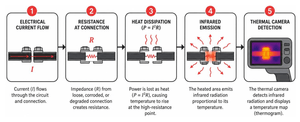
Thermal imaging relies on a simple scientific fact: electrical components almost always get hot before they fail. Every piece of operating electrical equipment emits invisible infrared radiation. An electrical thermal imaging inspection captures this radiation and converts it into a visual temperature map (a thermogram).
This diagnostic method is rooted in basic electrical principles. According to Ohm’s Law ($V = IR$) and the power law ($P = I^2R$), electrical power lost as heat increases with the square of the current ($I$) and directly with resistance ($R$). When an electrical termination loosens, corrodes, or degrades, its contact resistance increases. As electrical current flows through that high-resistance point, power is dissipated as intense localized heat ($I^2R$ power loss). If left unchecked, this heat breaks down insulation and melts conductors, leading to arc flashes or electrical fires. Recognizing these early thermal indicators is essential—learn more about the 5 Warning Signs Your Commercial Electrical System Needs Immediate Attention.
How Infrared Thermography Detects Hidden Electrical Faults
Modern thermal imaging cameras use microbolometer sensors to detect subtle variances in thermal radiation across the infrared spectrum. Rather than measuring contact temperature directly, the sensor reads radiant energy and translates it into distinct pixel color scales.
To help technicians quickly identify problem spots, thermography uses both qualitative and quantitative approaches:
- Qualitative Thermography: Focuses on pattern recognition. Technicians compare identical components operating under similar loads—such as three phases of a circuit—to look for visual anomalies.
- Quantitative Thermography: Measures exact surface temperatures and calculates precise temperature differentials ($Delta T$).
- Image Blending: Advanced imagers use dual-camera setups to overlay visible light edge details onto full radiometric thermal images, making it easy to identify specific breakers, lugs, or labels in complex panels.
Key Problems Detected by Electrical Thermal Imaging Inspection
An electrical thermal imaging inspection exposes hidden structural and electrical defects long before they trigger an breaker trip or catastrophic breakdown. According to InterNACHI guidelines, thermal imaging can reliably identify:
- Loose or Corroded Connections: High-resistance points that show up as sharp, localized hot spots at terminal lugs, busbar joints, or switch contacts.
- Unbalanced Phase Loads: Imbalance across three-phase systems where one phase leg carries excessive current and runs notably hotter than the others.
- Overloaded Circuits and Wiring: Excessive current draw that causes an entire conductor or circuit breaker to glow hot along its entire length.
- Harmonic Distortion: Overheating in neutral conductors and transformer cores caused by non-linear electronic loads.
- Arcing Hazards: Micro-arcing within degraded switchgear or contacts that creates irregular thermal spikes.
- Transformer Issues: Blocked cooling tubes in oil-filled transformers (visible as unexpectedly cold tubes) or severe coil overheating.
- Motor Winding Breakdown: Thermal hotspots on motor housings that signal internal insulation degradation or bearing friction.
Regularly scheduling these non-destructive scans keeps facility systems operating smoothly. Check out our guide on How to Tell When Your Home Needs an Electrical Safety Inspection for residential and commercial safety guidance.
Industry Standards: NFPA 70B Mandates and NETA Severity Thresholds
In recent years, industry standards have shifted infrared thermography from an optional maintenance practice to an official compliance mandate. The 2023 edition of NFPA 70B (Standard for Electrical Equipment Maintenance) officially changed thermography from a recommended practice to a firm requirement. Under NFPA 70B, facility owners must conduct annual infrared inspections on all general electrical distribution equipment, and mandatory six-month thermal inspections on critical equipment that could endanger personnel or cause catastrophic plant failure.
To evaluate thermal anomalies objectively, electrical contractors rely on NETA (InterNational Electrical Testing Association) Maintenance Testing Specifications. NETA guidelines define clear severity tiers based on temperature differences ($Delta T$):
| Severity Tier | Temperature Delta ($Delta T$) Baseline | Action Required |
|---|---|---|
| Low Severity | 1°C to 3°C rise over similar components under similar load | Repair at next scheduled maintenance window |
| Medium Severity | 4°C to 15°C rise over similar components under similar load | Repair promptly during upcoming planned shutdown |
| High Severity (Red Alert) | >15°C (27°F) rise over similar components OR >40°C (72°F) rise over ambient air | Immediate repair or replacement required |
Interpreting Thermograms and Evaluating Delta T Severity
Evaluating a thermal image requires more than just searching for bright yellow or white spots on a screen. Thermographers must evaluate both temperature elevation and heat distribution patterns.
A localized hotspot restricted strictly to a terminal screw indicates high contact resistance from a loose wire connection. Conversely, heat extending continuous along the length of a wire toward a load indicates an overloaded circuit or undersized wire.
Technicians must also look out for cold spots. An unexpectedly cold component in an energized panel often points to a blown fuse, an open circuit, or a blocked oil line shunting cooling fluid away from transformer windings.
In addition, thermographers must watch out for thermal reflections. Highly polished metals, such as bare copper or aluminum bus bars, act like mirrors to infrared radiation. They can bounce external heat—such as the thermographer’s own body heat—back into the camera, creating false hot spot readings.
Safety Protocols and Personal Protective Equipment for Live Inspections
Thermal imaging offers major non-contact safety advantages, but scanning live electrical equipment requires strict adherence to NFPA 70E arc flash safety standards.
When technicians must open panel doors to scan live conductors, they enter an arc flash hazard zone. Safe operation requires:
- Appropriate Arc Flash PPE: Flame-resistant (FR) clothing, arc flash face shields, insulated gloves, and safety glasses matching the panel’s arc flash hazard category.
- Approach Boundaries: Maintaining a minimum safe boundary of 4 feet from exposed, energized conductors under standard NFPA 70E guidelines.
- Infrared (IR) Inspection Windows: Installing permanent IR inspection windows into switchgear panels. These specialized crystal windows allow thermographers to scan interior connections with an IR camera without removing panel covers, completely eliminating arc flash risks and preserving cabinet integrity.
- Non-Contact Voltage (NCV) Verification: Testing panels with NCV tools and meters before opening doors or taking physical contact measurements.
Operational Best Practices and Execution Protocols
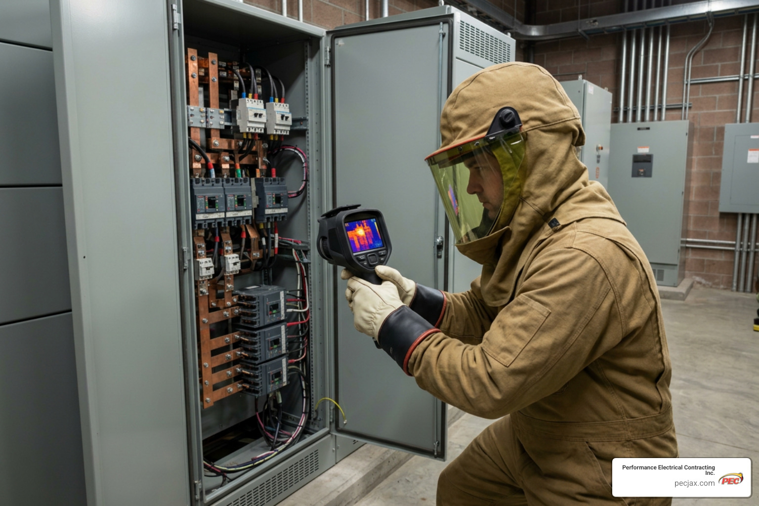
Executing an accurate thermographic audit requires careful attention to operating conditions. Scanning idle or de-energized equipment yields useless results, as thermal signatures only develop when current flows through resistance.
Prior to starting an inspection, review this essential pre-inspection safety and readiness checklist:
- Verify equipment is operating at nominal peak loads (minimum 40% threshold).
- Inspect panel enclosures externally for signs of active moisture, severe rust, or unusual buzzing.
- Don all required NFPA 70E-rated Arc Flash PPE before opening panel doors.
- Confirm infrared camera battery levels and clear cloud storage memory.
- Verify environmental variables (ambient temperature, wind speed, distance to target).
Load and Environmental Factors in Electrical Thermal Imaging Inspection
According to NFPA 70B guidelines, electrical equipment must operate at a minimum of 40% of nominal load for a thermal imager to detect connection defects or high-resistance hot spots. Operating at worst-case peak load is ideal, because heat generation scales with the square of the current ($I^2R$). For instance, doubling the load quadruples heat output, making minor connection flaws dramatically easier to see.
Outdoor or ventilated installations require adjusting for environmental factors:
- Convection Cooling: Wind velocities as low as 5 mph can cool exposed connections, masking severe internal hot spots.
- Solar Loading: Direct sunlight heats dark electrical enclosures and conduit, producing false thermal readings. Outdoor scans should be conducted at night, on overcast days, or out of direct sunlight.
- Surface Emissivity: Emissivity describes a material’s efficiency in emitting infrared energy, rated on a scale from 0.0 to 1.0. High-emissivity targets like dull, painted metal surfaces (0.90 to 0.98) yield accurate temperature readings. Low-emissivity bare metals like polished copper or aluminum reflect ambient radiation. Thermographers must manually adjust emissivity camera settings or apply matte electrical tape to reflective targets to capture accurate quantitative readings.
Equipment Selection for Electrical Thermal Imaging Inspection
Selecting the right thermal inspection camera depends on target distance, spatial resolution requirements, and reporting needs. Key hardware performance factors include:
- Thermal Sensitivity (NETD): Measured in millikelvins (mK), lower values indicate higher sensitivity. Sensitivity below <40 mK (0.04°C) captures minor temperature variations across delicate control wiring.
- Spatial Resolution & Optics: High detector resolutions (e.g., 320×240 or 640×480) coupled with telephoto lenses or rotating optical blocks allow inspectors to safely scan small overhead connections from far away.
Professional handheld options include the high-resolution Flir E8 Pro Pro-Series Infrared Camera with Ignite Cloud | Flir for cloud integration, or the rugged Fluke TiS20+ MAX Thermal Imaging Camera | Fluke equipped with IR-Fusion auto-blending technology.
For quick, everyday electrical troubleshooting, integrated test tools like the Industrial Thermal Imaging Multimeter with IGM™ | Flir allow technicians to locate hot spots visually using Infrared Guided Measurement (IGM) before taking standard digital multimeter electrical readings. For specialized long-distance utility inspections, high-end cameras like the T865 High-Performance Handheld Infrared Camera | Flir feature 180° rotating optics, while compact portable setups like the FOTRIC TP320A Portable Thermal Imaging Camera – FOTRIC US Official Store offer plug-and-play USB connectivity for smartphone-based field reviews. Budget-conscious facilities often rely on lightweight tools like the Fluke TiR105 or entry-level models like the Fluke TiS20+ MAX Thermal Imaging Camera | Fluke for routine, focus-free enclosure audits.
Predictive Maintenance Integration, Documentation, and ROI Analysis
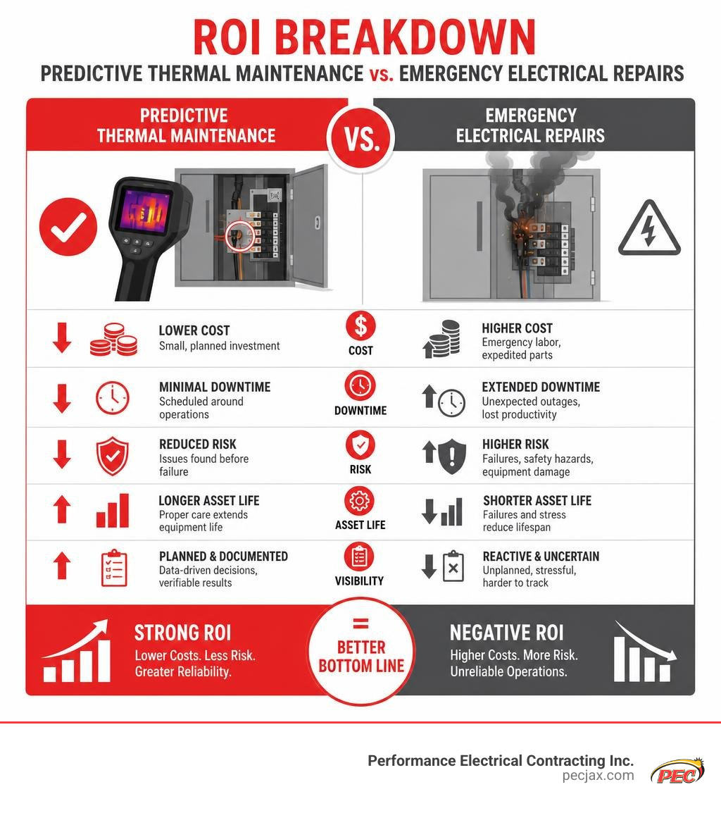
Integrating thermal inspections into an ongoing Predictive Maintenance (PdM) program turns reactive troubleshooting into a planned, cost-effective workflow. Capturing baseline thermal images of healthy equipment gives technicians a historical reference point to track gradual temperature increases over time.
Thermography also verifies repair quality. Capturing side-by-side “before and after” thermograms provides immediate visual proof that a loose connection was tightened or a damaged breaker was replaced successfully. Upgrading aging infrastructure often prevents these issues entirely—learn Why You Should Upgrade Old Electrical Outlets and Switches.
Financial Breakdown: Inspection Investment vs. Cost of Electrical Failure
The return on investment (ROI) for thermographic electrical maintenance is exceptional when compared against the high costs of unmanaged equipment failure:
- Motor Failure Example: Replacing an unmonitored 50 hp industrial motor costs roughly $5,000 in hardware and labor. If the failure causes 4 hours of facility downtime at $6,000/hour in lost productivity, the true total cost of failure hits $29,000. Catching an unbalanced motor connection early during a routine thermal scan costs a fraction of that amount.
- Transformer Aging: Operating a transformer just 10°C above its nameplate operating temperature reduces its insulation lifespan by 50%. Early thermal detection of oil leaks or cooling blockages doubles asset service life.
- Phase Voltage Unbalance: NEMA standards warn that motor voltage unbalance as low as 1% reduces motor efficiency and causes internal thermal stress, requiring motor de-rating to avoid burnouts.
- Insurance Discounts: Many commercial property insurers offer premium discounts or mandate annual infrared thermography to keep policies valid and reduce arc flash exposure.
Standardized Reporting and Compliance Documentation
Clear documentation ensures inspection findings are communicated effectively to management, facility owners, and safety auditors. Standardized thermographic reports should always feature:
- Radiometric Images: Full-color thermal images clearly highlighting thermal anomalies and temperature scale bars.
- Matching Visual Photos: Visible light digital photos taken from the exact same angle and distance to make component identification effortless.
- Data Metadata: Operating load percentages, surface emissivity settings, ambient temperature, distance to target, and exact equipment location tags.
- Severity Classifications: NETA-aligned risk prioritization (Low, Medium, Immediate Action Required).
- Voice and Text Annotations: Integrated voice memos synchronized through cloud platforms like FLIR Ignite or Fluke Connect for rapid executive summary reporting.
Frequently Asked Questions About Thermal Electrical Inspections
How often are thermal imaging inspections required on electrical systems?
Under the updated NFPA 70B 2023 guidelines, infrared thermography inspections are required at least annually for standard commercial and industrial electrical distribution systems. However, critical electrical assets—such as switchgear, main distribution panels, or emergency power systems whose failure could endanger personnel or halt vital operations—must undergo an electrical thermal imaging inspection every six months.
What minimum electrical load is required during a thermographic scan?
An electrical system must operate at a minimum of 40% of its nominal electrical load during testing. Higher operating loads yield better results because resistance-based heat dissipation increases exponentially with current flow ($I^2R$). Performing inspections during peak load conditions ensures that subtle connections flaws emit enough thermal radiation to be identified on camera.
Can thermal imaging cameras see through electrical panel doors?
No. Thermal imaging cameras detect radiant surface heat only; they cannot see through solid metal cabinets, plastic covers, or glass panel doors. To scan internal busbars, fuses, and terminations, qualified technicians must safely open enclosure doors under NFPA 70E guidelines, or scan the interior using pre-installed, non-destructive infrared (IR) inspection windows.
Conclusion
A comprehensive electrical thermal imaging inspection is one of the most effective, non-invasive ways to protect commercial property assets, maintain regulatory compliance, and optimize operational uptime. By uncovering hidden resistance, unbalanced phase loads, and overheating components long before they trigger an emergency outage, thermal scans turn costly emergency repairs into planned maintenance.
Adhering to NFPA 70B standards and leveraging NETA severity guidelines gives facility owners a clear roadmap for electrical reliability and safety.
At Performance Electrical Contracting Inc., our team of pre-qualified electrical professionals delivers value-driven electrical installation, routine maintenance, and compliance inspections across Jacksonville, FL, and the Southeast. Whether you need to bring your facility up to NFPA 70B standards or build a proactive maintenance plan, contact our team today to keep your property running safely, on time, and on budget.