
Low Voltage Garage Door Wiring: The Safe Starting Point
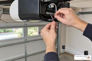
To wire a garage door opener safely, unplug it first. Run separate two-conductor, Class 2-rated wires from the opener to each safety sensor and to the wall control. Connect them to the terminals shown in your specific opener’s manual; terminal numbers and wire colors vary by model. Mount the sensors no more than 6 inches above the floor and the wall control at least 5 feet above any walking surface.
Keep these low-voltage wires separate from the 120-volt power wiring. Once connected, test the sensors and the door’s reversal feature before using the opener. Never bypass a safety sensor to make a door close. If the outlet, grounding, or power circuit needs work, call a qualified electrician.
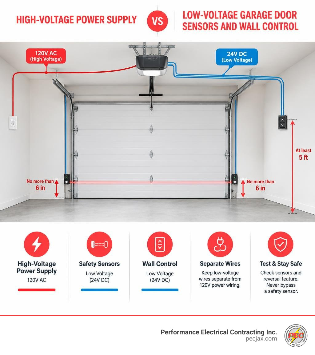
At Performance Electrical Contracting Inc., we work with both high-voltage power grids and delicate communication circuits across Jacksonville and the Southeast. We know that residential garage door automation brings both worlds together. Most modern residential operators—such as those manufactured by Chamberlain, LiftMaster, and Genie—rely on a 24V DC low-voltage circuit to operate their push buttons and safety features.
Under the Consumer Product Safety Commission (CPSC) and UL 325 mandates, every residential garage door opener manufactured since 1993 must incorporate an external secondary entrapment prevention system. The photoelectric safety eyes and wall consoles that manage this system rely on low voltage garage door wiring. When installed properly, these control lines ensure your overhead door moves reliably while keeping your family, vehicles, and pets protected.
Core Standards for Low Voltage Garage Door Wiring and Wire Selection
Low-voltage circuits do not pose the same shock risks as 120V branch circuits, but wire selection directly dictates overall system reliability. Modern operators use microprocessors that monitor tiny fluctuations in voltage or interpret digital communication pulses. Choosing undersized conductors or low-grade materials can lead to phantom reversal issues and mysterious diagnostic codes.
The National Electrical Code (NEC) governs low-voltage circuits under Class 2 regulations (Article 725). Class 2 cables must have a fire-resistant outer jacket labeled CL2, CL2R (riser-rated), or CL2P (plenum-rated). For home installations, standard two-conductor color-coded bell wire is the standard choice.
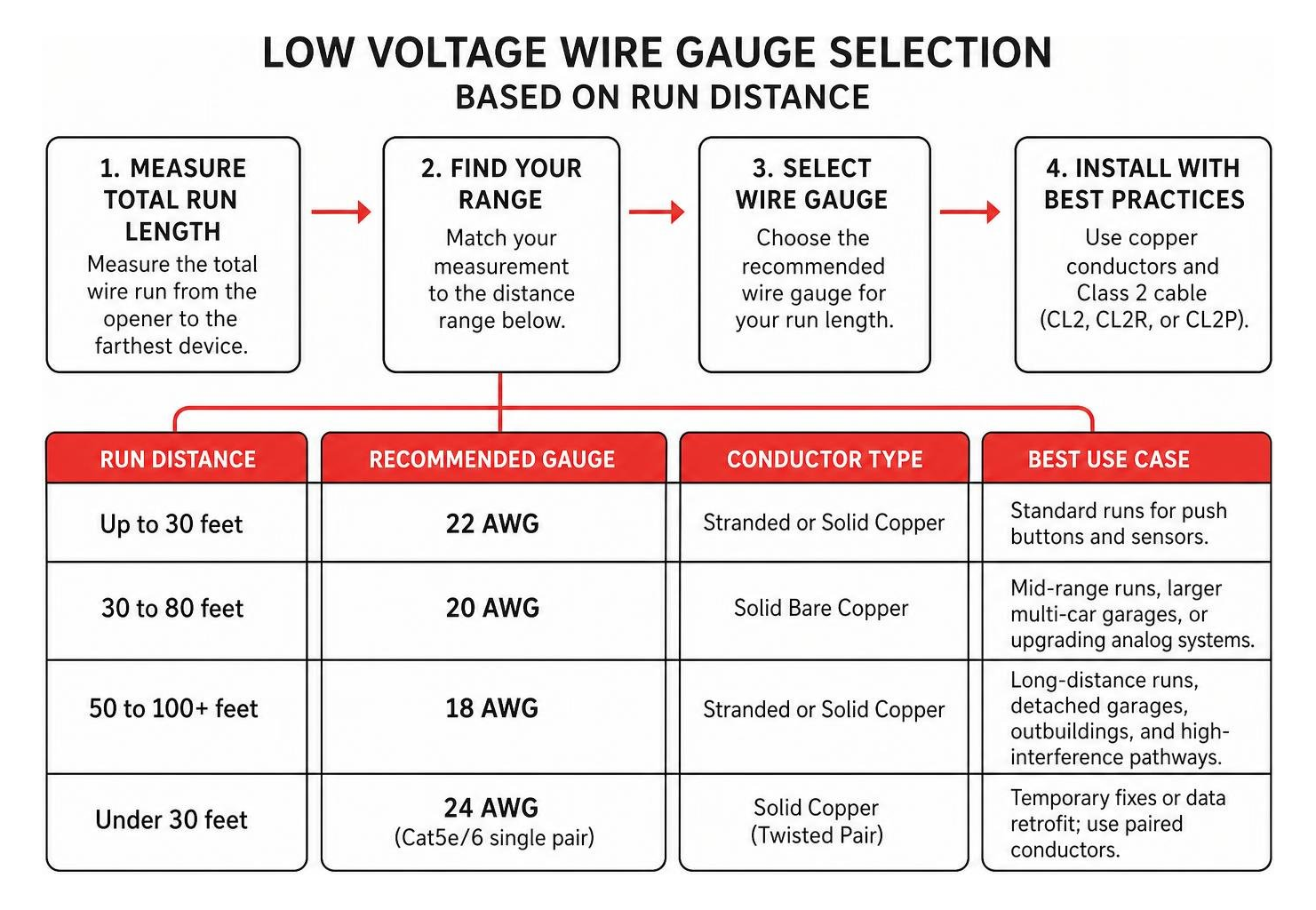
| Conductor Gauge (AWG) | Maximum Recommended Run | Conductor Type | Signal Integrity & Best Use Case |
|---|---|---|---|
| 22 AWG | Up to 30–50 feet | Stranded or Solid Copper | Standard runs for push buttons and sensors. Ideal for compact residential layouts. |
| 20 AWG | 30 to 80 feet | Solid Bare Copper | Mid-range runs, larger multi-car garages, or when upgrading older analog systems. |
| 18 AWG | 50 to 100+ feet | Stranded or Solid Copper | Long-distance runs, detached garages, outbuildings, and high-interference pathways. |
| 24 AWG (Cat5e/6 single pair) | Under 30 feet | Solid Copper (Twisted Pair) | Temporary fixes or data retrofit; requires paired conductors to mitigate voltage drop. |
Voltage drop is the gradual loss of electrical potential along a wire. For standard 22 AWG bell wire, runs under 15 feet experience less than 0.2V of drop at 24V DC. However, over a 50-foot run, that loss increases to between 0.4V and 0.7V.
While legacy analog systems rely on simple dry-contact closures, newer systems (such as Chamberlain and LiftMaster Security+ 2.0) transmit encrypted digital pulses over those same low-voltage terminals. Although digital boards tolerate mild voltage variations better than older analog circuits, high wire resistance can distort the pulse shape and trigger logic errors.
When selecting wire, always choose solid or stranded pure copper conductors. Avoid Copper-Clad Aluminum (CCA) wiring. CCA has higher internal resistance, breaks easily under terminal screws, and corrodes quickly in humid garage environments. If you are balancing panel upgrades alongside low-voltage additions, our residential electrical services provide the professional foundation your home needs.
Evaluating Alternative Cabling: Cat5e, Cat6, and Doorbell Wire
Homeowners frequently ask if they can repurpose leftover structured cabling (such as Cat5e or Cat6 Ethernet cable) or legacy doorbell wiring for garage door openers:
- Existing Doorbell Wire: Standard two-conductor doorbell wire is typically 18 AWG or 20 AWG solid copper. If the jacket is in good physical shape, free of breaks, and has solid continuity, it works well for wall consoles and sensors. However, older doorbell lines installed with metal staples behind drywall can suffer from concealed pinch points.
- Cat5e and Cat6 Cabling: Category cables contain four twisted pairs of 24 AWG (Cat5e) or 23 AWG (Cat6) conductors. A single 24 AWG strand is thin and fragile under screw-down terminals, increasing the risk of mechanical failure. If you use Cat cabling for runs over 30 feet, twist matching pairs together (e.g., solid blue with blue/white for positive, solid orange with orange/white for negative) to create an effective 20 AWG or 21 AWG conductor.
Rail-Mounted Trolley vs Wall-Mounted Jackshaft Wiring Configurations
The physical layout of your garage door opener determines how you plan and route your low-voltage wire paths. Consulting a verified Residential Garage Door Operator Pre-Wiring Diagram helps you map out your cable runs before mounting hardware.
- Rail-Mounted (Trolley) Operators: The motor head mounts directly to the center of the ceiling. Wire runs must travel up the door jambs, traverse the ceiling framing, and reach the central powerhead. Total low-voltage wire runs for trolley setups often measure between 25 and 45 feet depending on door height (a 7-foot door requires roughly 124 inches of rail clearance, an 8-foot door needs 136 inches, and a 10-foot door demands 166 inches).
- Wall-Mounted (Jackshaft / RJO) Operators: Jackshaft units mount directly to the wall beside the torsion spring shaft. This layout significantly shortens wire runs for safety sensors and the wall control on that side of the garage. However, jackshaft units require an additional low-voltage connection: the cable tension monitor. This switch mounts near the cable drum and trips if cable tension is lost.
Always leave 24 to 36 inches of slack wire at both the operator head and the safety eye junction points. This extra length ensures you can adjust bracket alignments or replace components without having to rerun hidden cables.
Step-by-Step Installation for Push Buttons and Sensors
Wiring your low-voltage accessories correctly requires careful stripping, neat cable management, and proper terminal connections.
Step-by-Step Low Voltage Garage Door Wiring for Safety Sensors
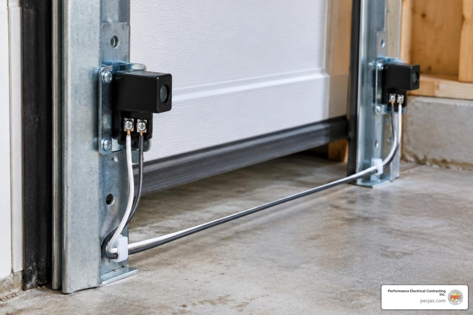
Photoelectric safety sensors form an invisible infrared beam across the entrance of your garage. When an obstruction breaks this beam while the door is closing, the motor reverses direction and returns to the fully open position.
- Mount the Sensor Brackets: Install the sending eye (amber/yellow LED) on one side of the door track and the receiving eye (green LED) on the opposite side. NEC and UL 325 standards mandate that the optical center of both lenses must sit no higher than 6 inches above the garage floor.
- Prepare the Conductors: Using precision wire strippers, remove approximately 1.5 inches of the outer cable jacket. Strip 7/16-inch of insulation from the individual conductors. Twist stranded wire ends tightly so no stray strands escape the terminal.
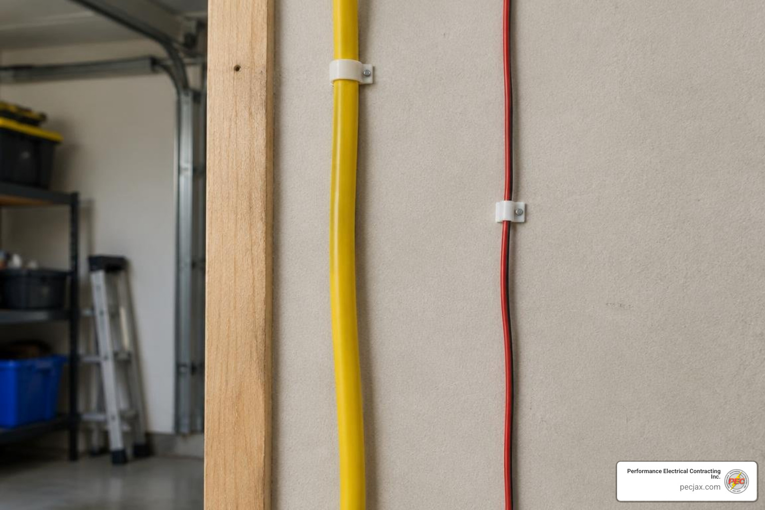
- Route the Sensor Cables: Run the bell wire up the door framing, keeping clear of moving tracks, torsion springs, and cables. Fasten the wire every 18 inches using insulated, non-metallic clips or low-voltage plastic staples. Never use standard steel construction staples, which can slice through insulation and create intermittent short circuits.
- Connect to the Operator Terminal Block: Bring both sensor runs to the powerhead terminal block. Most manufacturers use push-in quick-connect or screw terminals:
- LiftMaster / Chamberlain / Craftsman: Combine the solid white wires from both sensors and insert them into Terminal 2 (White/Common). Combine the white wires with black (or brown) stripes and insert them into Terminal 3 (Grey/Sensor).
- Genie / Overhead Door: Connect the two sensor wires to Terminals 1 and 2 (Genie Safe-T-Beam systems are generally non-polarized, but maintaining consistent color pairing makes troubleshooting much easier).
- Verify Polarity and Alignment: Restore power. The sending unit will display a steady amber light. Adjust the receiving unit until its green LED lights up solid and does not flicker.
Installing the Wall-Mounted Push Button and Control Console
The wall console operates the door, toggles overhead lighting, and manages vacation lockouts. Because this control panel commands the motorized door, its physical placement is subject to strict safety rules.
- Height Requirement: Mount the push button at least 5 feet (60 inches) above the floor or any adjacent step. This keeps the control out of the reach of small children and prevents accidental door operation.
- Line-of-Sight Placement: Position the console where the entire garage door is clearly visible during operation.
- Terminal Connections: Run a dedicated 2-conductor bell wire from the console to the motor head. Connect the solid color wire (often red or striped) to Terminal 1 (Red/Push Button) and the common wire (solid white) to Terminal 2 (White/Common).
Modern smart consoles feature microcontrollers that communicate over a digital bus. Reversing polarity on a digital console will prevent the LCD screen or backlights from turning on, often displaying an error code on the main powerhead.
National Electrical Code (NEC) Compliance and High-Voltage Safety
While low-voltage circuits carry minimal risk of electrical shock, proper physical separation from high-voltage lines is vital for fire safety and signal performance. A solid understanding of the complete guide to electrical safety code requirements ensures your home remains compliant and safe.
Routing Low Voltage Garage Door Wiring to Comply with NEC Rules
The National Electrical Code is unequivocal regarding Class 2 circuit isolation:
- Conduit and Enclosure Separation (NEC 725.136): Class 2 low-voltage wires must never share a conduit, raceway, electrical box, or drilled stud hole with 120V/240V power conductors (such as NM-B Romex). A failure in 120V insulation could energize the low-voltage lines, creating severe shock and fire hazards.
- Parallel Run Spacing: Maintain at least 2 inches of physical separation between low-voltage bell wire and unshielded 120V wiring runs. If a low-voltage wire must cross a 120V Romex cable, cross them at a 90-degree right angle to reduce electromagnetic interference (EMI).
- Low-Voltage Wall Boxes: When running wires behind finished drywall, terminate low-voltage cables into dedicated plastic low-voltage mounting brackets (open-back mud rings) rather than standard metal electrical gang boxes shared with line-voltage devices.
High-Voltage Power Supply: Dedicated Circuit, GFCI, and AFCI Requirements
Your low-voltage accessories rely on the main operator, which is powered by high-voltage branch circuitry. Consulting a standardized Wiring Diagram For Rail Trolley Garage Door Operators helps illustrate where high-voltage and low-voltage lines intersect at the powerhead.
Under current NEC standards (Articles 210.8 and 210.12):
- Dedicated Branch Circuit: A modern garage door opener requires a dedicated 15-amp (14 AWG copper) or 20-amp (12 AWG copper) 120V branch circuit. Sharing this circuit with high-draw workshop equipment or space heaters can cause voltage sags that reset the operator logic board mid-travel.
- GFCI & AFCI Protection: All garage receptacles require Ground-Fault Circuit-Interrupter (GFCI) protection, and many jurisdictions mandate Arc-Fault Circuit-Interrupter (AFCI) protection.
- Breaker vs. Receptacle Strategy: We recommend protecting the circuit via a dual-function CAFCI/GFCI breaker at the main electrical panel rather than plugging into a downstream GFCI receptacle on the ceiling. Motor start-up capacitor spikes can cause nuisance trips on standard GFCI receptacles.
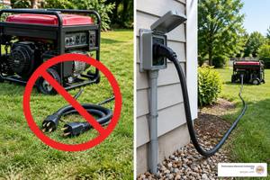
- Ceiling Outlet Placement: For trolley openers, install the 120V grounded outlet roughly 10 feet, 6 inches back from the garage header, centered within 12 inches of the rail. For wall-mounted jackshaft units, position the grounded outlet between 1.5 and 5 feet from the cable drum. Never use an extension cord as permanent power for an overhead door.
If you are upgrading your garage wiring or need advice on service panel capacity, our team can help you implement comprehensive electrical safety solutions tailored to your home.
Diagnosing and Troubleshooting Common Wiring Faults
When your garage door refuses to close, flashes its lights, or reverses unexpectedly, the problem usually traces back to a low-voltage wiring issue rather than mechanical motor failure.
If your electrical panel exhibits tripping issues or unexpected power loss while you are working, review these tips on identifying when your home needs an electrical safety inspection.
Deciphering Diagnostic LED Blink Codes and Polarity Errors
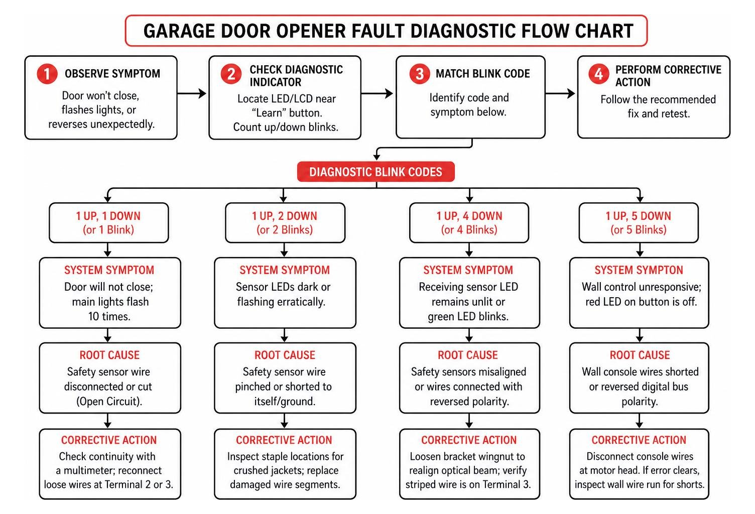
Most openers feature an LED diagnostic indicator near the “Learn” button or an LCD screen that flashes specific error codes to indicate low-voltage faults.
| Up/Down Arrow or Diagnostic Blinks | System Symptom | Root Cause | Corrective Action |
|---|---|---|---|
| 1 Up, 1 Down (or 1 Blink) | Door will not close; main lights flash 10 times. | Safety sensor wire disconnected or cut (Open Circuit). | Check continuity with a multimeter; reconnect loose wires at Terminal 2 or 3. |
| 1 Up, 2 Down (or 2 Blinks) | Sensor LEDs dark or flashing erratically. | Safety sensor wire pinched or shorted to itself/ground. | Inspect staple locations for crushed jackets; replace damaged wire segments. |
| 1 Up, 4 Down (or 4 Blinks) | Receiving sensor LED remains unlit or green LED blinks. | Safety sensors misaligned or wires connected with reversed polarity. | Loosen bracket wingnut to realign optical beam; verify striped wire is on Terminal 3. |
| 1 Up, 5 Down (or 5 Blinks) | Wall control unresponsive; red LED on button is off. | Wall console wires shorted or reversed digital bus polarity. | Disconnect console wires at motor head. If error clears, inspect wall wire run for shorts. |
Resolving Micro-Shorts, Sunstrike Interference, and Damaged Insulation
Beyond basic wiring disconnections, several elusive field conditions can disrupt low-voltage controls:
- Staple-Induced Micro-Shorts: When a steel staple is driven too tightly against a wall stud, its metal bridge can press through the outer PVC insulation, lightly contacting the copper conductor inside. When the door operates, vibration causes the conductors to intermittently bridge, creating a micro-short that triggers a sudden safety reversal. Fix: Pull out metal staples and install plastic-sheathed insulated cable saddles.
- Sunstrike Blindness: Low-voltage safety sensors communicate via infrared light. Direct sunlight hitting the receiving eye lens (the green LED unit) can overwhelm the optical transistor, mimicking a beam obstruction. Fix: Swap the physical positions of the sending and receiving units so the receiving lens faces away from the sun, or slide a 3-inch section of opaque 1/2-inch PVC pipe over the lens hood as a glare sunshield.
- UV and Moisture Damage: Sensor wires running along bottom floor plates or masonry walls are exposed to humidity, weed trimmers, and pets. If a wire is severed, fix it with solder-seal heat-shrink butt connectors. These combine low-temperature solder with adhesive-lined heat shrink tubing to seal out water and prevent oxidation. Avoid open twist-on wire nuts near floor level.
Frequently Asked Questions About Garage Door Wiring
What gauge wire is best for garage door sensors and wall controls?
For runs under 50 feet, 22 AWG two-conductor solid or stranded copper bell wire is the industry standard and comes supplied with most new openers. For runs between 50 and 100 feet—or for detached garages—upgrade to 18 AWG copper wire to prevent voltage drop and keep signal attenuation within manufacturer tolerances. Always select Class 2 (CL2) fire-rated cable.
Can I splice garage door sensor wires if they are cut or damaged?
Yes, but how you splice them matters. Avoid using standard twist-on wire nuts or wrapping exposed wire in electrical tape, as garage vibrations and humidity will eventually cause these connections to loosen or corrode. Instead, use waterproof solder-seal heat-shrink connectors or gel-filled IDC telecom crimps (B-connectors) to maintain strong continuity and keep moisture out.
Why won’t my garage door close even though the sensor LEDs are lit?
Solid LEDs confirm that the sensors have power and approximate optical alignment, but intermittent faults can still occur. Common culprits include:
- Vibration misalignment: The sensors are barely aligned, and motor vibration shakes them out of line as soon as the door starts rolling.
- Staple pinches: A pinched wire creates a brief micro-short when the frame vibrates.
- Loose terminal connections: Screws on the terminal block may have loosened over time. Perform a light “tug test” on each conductor at the motor block to ensure it is clamped securely.
Code-Compliant Reliability for Your Home
Wiring the low-voltage components of a garage door opener is a straightforward DIY project once you follow the basic rules: choose quality copper conductors, maintain consistent polarity, secure cables with insulated fasteners, and keep low-voltage control circuits safely separated from high-voltage 120V lines.
If your installation requires adding a dedicated 120V power circuit, fitting panel-level GFCI/AFCI breakers, or routing wiring across complex commercial structures, our licensed team is ready to help. Performance Electrical Contracting Inc. provides premier electrical installations across Florida and the Southeast. Contact us today or read our guide on hiring low-voltage cabling contractors to ensure your property’s electrical infrastructure is safe, dependable, and built to code.